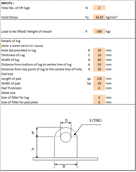
The theoretical calculations. Key Words: FEA, lugs, pin, margin of safety, Vonmises stress, ANSYS. Lugs are connector type elements used as structural supports for pin connections. A lug, also known as a lifting lug is essentially a plate with a hole in it where the hole is sized to fit a clevis pin. Example of an Overhead Lifting Lug kip ≡ 1000⋅lb There is very little published information available on the subject of the design/analysis of lifting lugs. Therefore, design engineers are left without adequate technical guidance on this subject. The following provides a systematic method. Introduction by Clement Rajendra, PE.
Lifting Lugs Manual Calculation Pdf
Lug Dimensions: Height of hole centreline, H = Width of Lug, W L = Radius of Lug, R = Diameter of Hole, DH = Thickness of Lug, tL = Allowable Stresses: Lug Material Allowable Tension Stress, 0.6 x Fy = Allowable Shear Stress, 0.4 x Fy =
20000 kgs = 1 2.0 60 degrees 40,000 kgs =
44,092 lbs
88,184 lbs
120 mm = 300 150 60 28
4.72 inch
mm = mm = mm = mm =
11.81 5.91 2.36 1.10
A 36 Fy = 1,519 Kg/cm2 = 1,012 Kg/cm2 =
inch inch inch inch
36,000 psi 21,600 psi 14,400 psi
DH/2R = 0.20 Stress-Concentration Factor (near hole), K = 2.5 (for flat plate with centrally located circular hole in tension based on DH/2R value)
Tension Stresses in the Lug: Weight in each Lug, W = Cable Tension at Lug, F = Inertia Moment of Lug, IL = Stress at Lug to Beam Joint = ST = F.cos (q). H.(W L/2)/IL +
40,000 kgs = 46,188 kgs = 6,300 cm4 = 1,136 Kg/cm2 =
F.sin(q)/(W L.tL) Stress at near the hole = ST = K .F. sin (q) / [(2.R -DH).tL]
88,160 lbs 101,798 lbs 151.36 in4 16,153 psi Safe
Ratio =
Safe
21,160 psi Ratio = 97.96%
Safe
3,909 psi Ratio = 27.15%
Safe
4,887 psi Ratio = 33.93%
1,488 Kg/cm2 =
74.78%
Shear Stresses in the Lug: Stress at Lug to Beam Joint = SS = F.cos(q) / (tL.W L)
275 Kg/cm2 =
Stress at near the hole = SS = F.cos(q) / [(2.R - DH).tL]
344 Kg/cm2 =
Page 5
Stresses in Weld: The calculation used is conservative as it only includes top fillet welds (actual stresses are lower) Leg size of fillet weld, LW = use 45 degree fillet weld Throat size of fillet feld, tW =
17.68 mm =
0.70 in
Length of weld, Ww1 = 2.W L + 2.tL
656.0 mm =
25.83 in
1,743.4 mm =
68.64 in
530,330 mm3 =
32.36 in3
Length of weld including welding in web of beam, W
25.0 mm =
0.98 in
W w2 = W w1 + W L + 2.Hbeam Section Modulus of weld lines, SW = SW= tw.W L2/3 Efficiency of weld, n = Allowable Load on weld Tension Stress at the weld = ST=[F.cos(q).H/SW+ F.sin(q)/ (W w2.tw)] / n Shear Stress at the Weld = ST=[ F.cos(q)/ (W w1.tw)]/ n
100% 675 Kg/cm2 =
9,600 psi
652 Kg/cm2 =
9,276 psi Safe
Ratio =
Safe
2,832 psi Ratio = 29.50%
30.86 Kg/cm2 =
96.62%
Lifting lug calculation.xls - Free download as Excel Spreadsheet (.xls), PDF File (.pdf), Text File (.txt) or read online for free. Lifting-Lug-Calculation.pdf - Free download as PDF File (.pdf), Text File (.txt) or read online for free. Scribd is the world's largest social reading and publishing site. Open navigation menu.
Lifting Lug Design Calculation Pdf
9.3.1 Lug Bearing Strength Under Uniform Axial Load. The bearing stresses and loads for lug failure involving bearing, shear-tearout, or hoop tension in the region forward of the net-section in Figure 9-1 are determined from the equations below, with an allowable load coefficient (K) determined from Figures 9-2 and 9-3.